

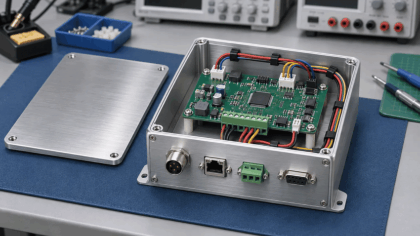
Box build assembly is the process of combining populated circuit boards, wiring, mechanical parts, and an enclosure into a complete electronic unit. It extends beyond PCB assembly to include the connections, configuration, and checks that make those parts work together. Depending on the product, the finished unit may be a small sensor module, a desktop instrument, or a larger control assembly.
How Box Build Assembly Differs from PCB Assembly
PCB assembly creates the populated board; box build assembly integrates that board into the product around it. A PCBA can pass its specified board tests yet still fail after installation because a cable is miswired, a connector is not fully seated, or the enclosure interferes with a component.
The difference is easiest to see in the deliverable:
- PCB assembly: A board with installed electronic components, inspected and tested to the agreed board-level requirements.
- Box build assembly: An integrated unit with its mechanical and electrical connections completed, plus the configuration and final checks defined for that product.
Manufacturing services described as Box Build Assembly can therefore cover much more than placing a board inside a housing. The scope should identify where integration ends: a wired subassembly, a tested instrument, and a packaged end-user product are different deliverables.
What Parts Go into a Box Build?
A typical box build combines electronics, interconnections, and mechanical support, with additional parts determined by the application. The bill of materials should include the small assembly items as well as the major modules.
- Printed circuit board assemblies: Control, sensing, communication, or power electronics. Some products use one board; others connect several boards or modules.
- Enclosure and mounting hardware: The housing, brackets, spacers, fasteners, and insulating pieces that position and protect the electronics.
- Cables and wire harnesses: Power and signal connections between boards, panels, and other components. Connector pin assignments and cable routing matter as much as cable length.
- Power components: An internal supply, converter, battery connection, or power inlet, depending on how the product receives energy.
- User interfaces: Displays, switches, indicators, and external connectors that allow people or other equipment to interact with the device.
- Thermal and protective parts: Heat sinks, fans, thermal interface materials, shields, or seals where the design requires them.
- Identification and packaging: Product labels, serial numbers, accessories, and protective packing needed for the agreed delivery condition.
Firmware is not a mechanical part, but its revision belongs in the build configuration. Two physically identical units can behave differently if they contain different software or calibration settings.
The Box Build Assembly Process
The process moves from a controlled set of documents to checked subassemblies, integrated hardware, and a verified finished unit. The exact sequence depends on access: a connection that becomes hidden after a panel is fitted must be completed and inspected earlier.
- Release the build information. Establish the approved bill of materials, mechanical drawings, wiring instructions, firmware, and acceptance procedure. Resolve conflicting revisions before parts reach the assembly station.
- Receive and identify materials. Check supplied items against the released parts list and segregate incorrect or damaged material. Identify which items are customer-supplied and which are purchased for the build.
- Prepare subassemblies. Assemble and check the boards, cables, and other modules required by the work instructions. Catching a wiring defect before installation avoids dismantling a finished enclosure later.
- Install mechanical and electronic parts. Fit supports and modules in the planned order, using specified fasteners and tightening requirements. Confirm clearance around the board, connector access, and the intended thermal contact surfaces.
- Connect and secure the wiring. Follow the wiring diagram, confirm connector engagement, and apply the specified strain relief. Check that closing the enclosure will not trap a cable or force it against a sharp edge.
- Load and verify the configuration. Program the approved firmware where required, apply settings, and perform specified calibration. Verify the resulting version or configuration rather than treating a successful download as sufficient evidence.
- Inspect, test, and release the unit. Complete accessible internal checks before closure, then perform the required final tests in the specified assembled condition. Record the result against the unit identity before labeling and packing.
A pilot build helps expose instructions that look complete on paper but are difficult to follow at the bench. For example, it may reveal that a screwdriver cannot reach a fastener after a display is installed, requiring an assembly-sequence change before repeat production.
Which Tests Does a Finished Box Build Need?
A useful test plan links each check to a requirement and a failure it can detect. Visual inspection, wiring tests, and functional tests provide different evidence; none automatically replaces the others.
Visual and Mechanical Inspection
Visual inspection checks whether the assembly matches its drawings and workmanship criteria. Typical checks include connector seating, cable routing, label accuracy, and the absence of loose hardware inside the enclosure.
Mechanical checks address features that appearance alone cannot establish, such as a specified fastening torque or critical dimension. Record these at the appropriate assembly stage, especially if the feature will become inaccessible after closure.
Wiring and Electrical Checks
Continuity and connection checks establish whether intended electrical paths exist and whether wires reach the correct terminals. A harness test can also look for unintended connections between circuits; simply checking that one wire conducts does not prove that the entire harness is correct.
Insulation resistance, dielectric withstand, and protective-earth tests answer different questions and apply only where required by the design and relevant product requirements. Their test conditions must be defined for the equipment under test; high-voltage testing is not a generic step to apply indiscriminately to connected electronics.
IPC/WHMA-A-620 provides requirements and acceptance criteria for cable and wire harness assemblies. Where it is specified, the build documentation should identify the applicable revision and class, while retaining the product-specific wiring and test requirements.
Functional Testing
Functional testing checks the assembled product’s response to defined inputs under defined conditions. A power indicator proves little about whether the installed signal path, controls, and outputs work correctly.
Test through the finished unit’s external interfaces where practical, so the test includes the installed connections. For an illustrative sensor controller, the procedure might require the following:
- Apply a known input at the external sensor connector.
- Compare the reported reading with the product’s specified tolerance.
- Check the relevant output or alarm response.
- Confirm that configuration is retained after the prescribed restart.
This example tests more of the assembled path than connecting directly to the bare board. It still covers only the functions and conditions included in the procedure, rather than proving every possible operating state.
Environmental and Extended Testing
Temperature, vibration, sealing, or extended-operation tests are included when the product requirements call for them. Some belong to design qualification, while others may be production screens performed on every unit or a defined sample.
Burn-in is not automatically necessary for every box build, and a brief room-temperature functional check does not establish performance across an entire environmental specification. The test plan should distinguish qualification evidence from routine production acceptance.
What Makes a Build Repeatable?
Repeatability depends on controlling the product configuration and defining what counts as a pass. A reference sample helps explain appearance and routing, but it should not be the only place where important requirements exist.
The manufacturing package should make four things explicit:
- Build identity: Part numbers and revisions for the unit, its subassemblies, and the approved firmware.
- Assembly requirements: Drawings and instructions for fit, wiring, fastening, and features that need inspection before closure.
- Acceptance criteria: Test setup, input conditions, measurement limits, and the actions required after a failure.
- Traceability: The unit identifier, test outcome, and required records of changes, repairs, or configuration.
Manufacturing scope needs the same clarity as technical documentation. A PCB fabrication and assembly supplier such as ORINEW TECHNOLOGY CO.,LIMITED may be involved in the electronics portion, but the project documentation must still assign responsibility for enclosure parts, firmware release, and final acceptance. A service name alone does not define those handoffs.
Repair records should preserve the original failure as well as the subsequent result. After rework, repeat the affected checks and any other tests required by the approved procedure; a single successful retry should not erase an unexplained intermittent fault.
FAQ
Does box build assembly always produce a finished consumer product?
No, it can produce a complete end-user product or an integrated subassembly that goes into a larger system. The agreed delivery condition determines whether accessories, retail packaging, and end-user configuration are included.
Does every box build need custom cables and enclosures?
No, standard housings and off-the-shelf cables can be suitable when they meet the design requirements. Custom parts become useful when fit, connector arrangement, routing, or environmental constraints cannot be met adequately with standard items.
Is PCB testing enough for a box build?
No, board testing does not verify connections or mechanical conditions introduced during final assembly. The finished unit needs checks that cover its installed interfaces and required system behavior.
Does passing a functional test prove regulatory compliance?
No, a functional test demonstrates only that the tested behavior meets the defined limits under the stated conditions. Product safety, electromagnetic compatibility, and other applicable requirements may need separate assessment and evidence.
What determines box build assembly time?
Assembly time depends on the number of operations, access to connections and fasteners, configuration tasks, and required test duration. Overall project lead time also includes parts availability and the readiness of drawings, fixtures, and approved instructions.
Conclusion
Box build assembly turns individual electronic and mechanical parts into an integrated unit with a defined configuration and acceptance result. Its quality depends on both correct assembly and tests that cover the finished product’s actual interfaces. Before releasing a build, trace one critical function from its external connector through the internal wiring to the recorded test result, and close any gap in that path.
