

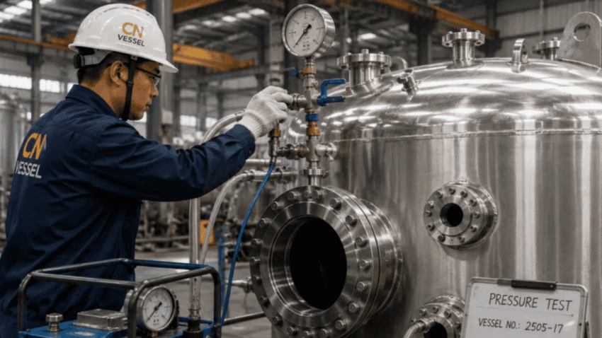
A digital layout can show pressure vessels sitting comfortably inside a building while leaving nozzle fit and maintenance space unresolved. The shell clears the wall, yet a flange faces a column. A manway cover opens, but the adjacent pipework occupies the place where a technician would stand. These are useful questions to raise while the arrangement can still be changed.
For buyers reviewing equipment on screen, the practical task is to inspect movements as well as objects. Consider how mating pipework reaches a nozzle, how a tool reaches a fastener and where a removed component goes. A polished view of installed equipment rarely answers all of those questions. The following checks turn a digital model into a more useful discussion between the purchaser, fabricator and installation team.
Start with the surroundings of pressure vessels
Review the vessel in its intended setting, including the walls, beams, platforms, neighbouring equipment and approach routes that constrain its position and determine whether people can perform the installation and maintenance tasks proposed for that location. The surrounding plant matters. An isolated vessel model cannot answer those access questions.
Ask which parts of that setting are confirmed. A measured existing column and a provisional piping route deserve different treatment. If an apparent clearance depends on moving pipework that nobody has agreed to move, record that dependency before accepting the layout. Otherwise, a plausible image can quietly become an installation commitment.
For replacement pressure vessels, check the current site arrangement against the available survey or drawings. Make uncertain dimensions visible in the review notes. A clear view of incomplete information is more useful than filling gaps with convenient geometry.
Inspect the whole nozzle connection, including the fasteners
Nozzle fit involves more than matching centre lines. Review the proposed mating flange, gasket space, bolts and nearby fittings as an assembly, because a connection that appears aligned in the model may leave no practical approach for inserting a bolt or using the intended tightening tool. Inspect the joint at working scale.
Use a close view to inspect the joint, then pull back to examine the approach. Does a nearby support obstruct the tool? Will the connected valve crowd an adjacent nozzle? Ask the piping team and equipment supplier to resolve the actual connection details before treating a generic model component as an accepted interface.
A useful review comment names the obstruction and the task it prevents. “Check clearance” leaves the next person guessing; “confirm access to the lower flange fasteners behind the support” identifies a physical question. Any proposed nozzle relocation still needs the responsible engineer’s assessment of its wider design consequences.
Give storage tanks a workable drain and access arrangement
Storage tanks bring attention down towards outlets, supports and the floor. Follow the intended drain connection through its attached valve and onward piping. Check where the operator approaches the valve and whether nearby steelwork leaves the connection accessible for the planned maintenance task.
Change the viewing angle. A plan view may show an unobstructed route while concealing a low connection tucked behind a support, so inspect the arrangement from the side and ask the operator to identify any temporary hose or collection device that must fit there. Reserve space for that actual item.
Do not infer drainage performance from the visible outlet position alone. The process and equipment engineers must assess the selected arrangement against the fluid and operating requirements. The layout review contributes a narrower but necessary answer: can the agreed components be reached, connected and serviced in their proposed positions?
Review manways with the cover open
A closed manway is an easy object to fit into a model. Its service condition is more demanding. Show the cover in the position required by the selected opening arrangement, together with any handling equipment and the working area outside the opening. Confirm these details with the supplier instead of assuming a convenient hinge or lifting method.
Now inspect the technician’s approach. Even where nearby pipework leaves the cover free to move, it may block access to the fasteners, while a platform that provides a convenient approach can put its handrail directly across the movement needed to open the vessel. Check the complete task before relocating a component.
Space at a manway is a layout consideration, not permission to enter a vessel. Entry and maintenance procedures need their own site assessment. Keep that distinction clear when recording what the geometric review has actually established.
Reactors need room above their installed outline
For reactors with removable internal equipment, ask the supplier to describe the intended removal method. An agitator assembly that fits during operation may need an overhead path during maintenance. Show the relevant component through that movement, including any handling arrangement the project intends to use.
ChannelVessel’s public enquiry guidance requests details of jackets, coils, agitators and internals, alongside orientation, space restrictions and interfaces. Its listed product range includes reactors, pressure vessels and storage tanks, making these configuration details relevant inputs to a custom equipment enquiry.
Look beyond the nearest beam. Trace the assembly to the place where it would be supported after removal, and have the operations team assess any sequence that depends on dismantling another component before the assembly can reach the maintenance area. Empty space overhead is only the beginning.
Heat exchangers require a construction-specific removal route
Heat exchangers should be reviewed according to their selected construction and maintenance method. Ask what is intended to open or withdraw, which connections must be disconnected and what temporary support is required. Avoid assigning a generic removal envelope to every exchanger merely because the models have similar outlines.
Follow the part beyond the equipment footprint. Once the supplier has identified what must move, trace it from its housing to a suitable working position, checking for columns and other obstructions along a route that must accommodate handling as well as the initial withdrawal. Maintenance also needs a destination.
If the route crosses an access aisle, discuss how that space would be managed during the task. Record any dependence on moving adjacent equipment. The purchaser can then judge the maintenance arrangement before the installation makes a difficult sequence unavoidable.
Process skids need access through the frame
In process skids, surrounding items can belong to the same package and still obstruct one another. Inspect valves, instruments and vessel connections through the frame. A clear view obtained by hiding the frame on screen is useful for investigation, but restore it before judging access.
Reading an instrument and replacing it are different tasks. If its display faces the aisle but its removal direction points into a cross-member, ask the package supplier which nearby components must be disconnected and have the operations team assess whether that sequence suits the intended maintenance practice. Inspect both conditions.
The public description of ChannelVessel custom pressure equipment includes process skids combining vessels, pumps, valves, piping, instruments and heat equipment. The manufacturer requests drawings, process conditions and interface requirements for custom enquiries; these are equipment specification inputs, rather than a description of software services.
Carry the review beyond the skid edge. External pipes and site structures can occupy space that appeared available in the supplier’s package model.
Keep geometric acceptance separate from pressure design
A digital model helps reviewers locate spatial conflicts when the relevant objects and movements are represented. It cannot establish the suitability of pressure-retaining parts merely by showing that they fit. Keep the layout decision alongside the engineering decisions it depends on.
ASME’s published pressure-vessel construction scope covers design, fabrication, inspection, testing and certification for internal or external pressure exceeding 15 psig. This describes the standard’s scope; it does not demonstrate that an individual manufacturer holds certification.
A geometric improvement can affect other requirements. When reviewers suggest moving a nozzle or changing a support to gain maintenance space, keep the proposal unresolved until the responsible engineer has assessed its technical consequences and the accepted arrangement can be reviewed with the surrounding equipment visible. A moved object is not an approved change.
Close the review by walking through a maintenance task
Select a real planned task and explain it using the proposed layout. Start with the approach, identify what must be disconnected, follow the component’s movement and finish where it will be serviced. This makes assumptions easier to challenge than a presentation consisting only of attractive equipment views.
- Show the mating parts and tool approach for the connections being reviewed.
- Display covers and removable components in their relevant service positions.
- Identify the structures, supports and neighbouring equipment along each removal route.
- Record unresolved clearances with a decision owner and the information needed.
The useful outcome is an arrangement whose practical limitations are understood before drawing release. Purchasers should be able to explain how the pressure equipment connects, how maintenance personnel reach it and how the specified removable parts leave it. Where that explanation still depends on an assumption, the digital layout has identified the next question to settle.
